With this old mill’s spindle motor up and running with the Variable Frequency Drive (VFD), I started wondering if there was a way to control the VFD with the mill’s Allen Bradley 8400MP controller. To learn more about how I wired the VFD to power and spindle motor, visit my Harnessing the Variable Frequency Drive page.
If you just want to skip my long-winded nerdy explanation about how all this stuff works, scroll down to the bottom of this page and play the video. Otherwise keep reading, and know you’ll get there eventually.
So I ran the mill for several weeks with the VFD essentially controlling the spindle motor as a separate system. What I mean by this is that the spindle motor was not being controlled by the Allen Bradley 8400MP in any way.  Although this wasn’t the end of the world, I began to get tired of walking around the mill’s table and over to the VFD’s interface to turn on the spindle motor, then walking back over the mill’s control console. I suppose I could have installed the VFD much closer to the mill’s control console, such that I wouldn’t have to walk back and forth, but that would have required power wiring running greater distances than I care for. Additionally, with the VFD and mill’s control console being separate systems, hitting the mill’s emergency stop button would do absolutely nothing to stop the spindle motor. From a safety perspective I didn’t like this either.
While learning how to connect the VFD to power and the spindle motor, I also read a bit about how to control the VFD remotely in the VFD’s manual. By remotely I mean, not using the interface on the VFD itself. Turns out this particular VFD has a control terminal strip that can be used to interface it with other electronics. In this case the other electronics would be the Allen Bradley 8400MP control (AB control moving forward). This particular VFD has a lot of options for controlling a motor via it’s terminal strip interface. However, in the mill spindle motor use case scenario, the following are probably the most realistic – listed in my opinion from basic to advanced:
- Motor start/stop – This is pretty much self-explanatory but it’s important to realize that in this case, the motor can only rotate in one direction (at one speed) or be off/stopped. This requires (1) digital output/relay from the AB control.
- Motor start/stop with speed control – In this case the motor can be controlled to rotate in one direction including speed control or be off/stopped. This requires (1) digital output/relay and (1) analog control output from the AB control.
- Motor forward/reverse/stop – In this case the motor can be controlled to rotate in either direction (at one speed) or be off/stopped. This requires (2) digital outputs/relays from the AB control.
- Motor forward/reverse/stop with speed control – In this case the motor can be controlled to rotate in either direction including speed control or be off/stopped. This requires (2) digital outputs/relays and (1) analog output from the AB control.
So now that the available remote VFD control options are understood, I had to determine if the outputs available through the AB control would be compatible. Getting the AB control’s digital outputs/relays to turn the spindle motor on in either forward or reverse via the VFD is pretty straight forward. After all, digital outputs wired to relays are really just switches. However, making sure the AB control’s analog output is compatible with the VFD’s analog input takes some more careful investigation. The VFD requires an analog input of 0 to 10VDC to change the speed of the motor from 0% to 100% (0VDC = 0% RPM, 10VDC = 100% RPM). Turns out there is a linear relationship between voltage and % RPM, so for example, 5VDC causes the VFD to control the spindle motor to 50% RPM. If all this percentage RPM stuff is confusing you, look at my Harnessing the Variable Frequency Drive page. Anyway wouldn’t you know it, by using my digital multimeter, I was able to measure the AB control’s analog voltage outputs 0 to 10VDC. In this case I either lucked out or there is some industry standardization stuff that worked out in my favor. How cool is that!? Maybe it’s better to be lucky than good?
Okay, enough of that. Given my findings above, it would be pretty silly to pick anything except option 4 as described above. So if you’re still reading, the follow describes how to wire it all up.
As previously established, the (2) digital outputs/relays, originally connected to this old mill’s spindle motor contactors, are used to tell the VFD to turn on the spindle motor in either the forward or reverse direction. The analog output is used to tell the VFD the speed (RPM) of the spindle motor as it rotates in either the forward or reverse direction. The following image shows the available VFD connections, the highlighted ones are the ones I’ve used. Additionally, the image includes a wiring diagram showing the exact connections between the AB control to the VFD.
The following is an actual picture of the VFD wired to match the wiring diagram above. It might not be obvious, but the wires with the red and black insulation are actually part of a shielded cable. These wires are connected to the analog voltage output of the AB control (find DR7 in the wiring diagram above). I’m told it’s especially important to protect analog control lines from noise, so I selected cable that includes foil shielding. This cable also includes a bare wire that runs along the inside of the foil shield. The bare wire makes contact with the foil shield along the length of the cable. This bare wire is often referred to as a drain wire, and its purpose is to provide a simple way of connecting the foil shield to ground. The theory is that the electrical noise absorbed by the foil shield is dissipated to ground and kept out of the signal wires. If you’re paying attention, you might be wondering where I’ve attached the drain wire to ground, because it clearly isn’t shown in the picture. There is a point to be made here, I’ve ONLY connected the drain wire to the ground available in the AB control (DR7 connector 3) on purpose. In general, shield drain wires should only be connected at one end of the cable, this is to avoid ground loops – which could create even bigger problems than the noise we’re trying to prevent!
Here’s a picture of the AB control’s analog connection point, DR7. To be clear, I didn’t discover the AB control’s analog output intended to control the speed of a spindle motor by complete chance. I used the Allen Bradley 8400MP installation manual I purchased as a guide ($100). No worries about copy-write issues, its been out of print for a long time. Lucky for you, I’ve made the installation manual available to download from this website for free. The spindle speed analog connection point (DR7) can be found on page 55 of the installation manual. Notice the cable’s shield drain wire I made a big deal about previously is connected here.
Now here’s the last picture I need to show you of the AB control’s digital output/relays. This picture really just shows the relays.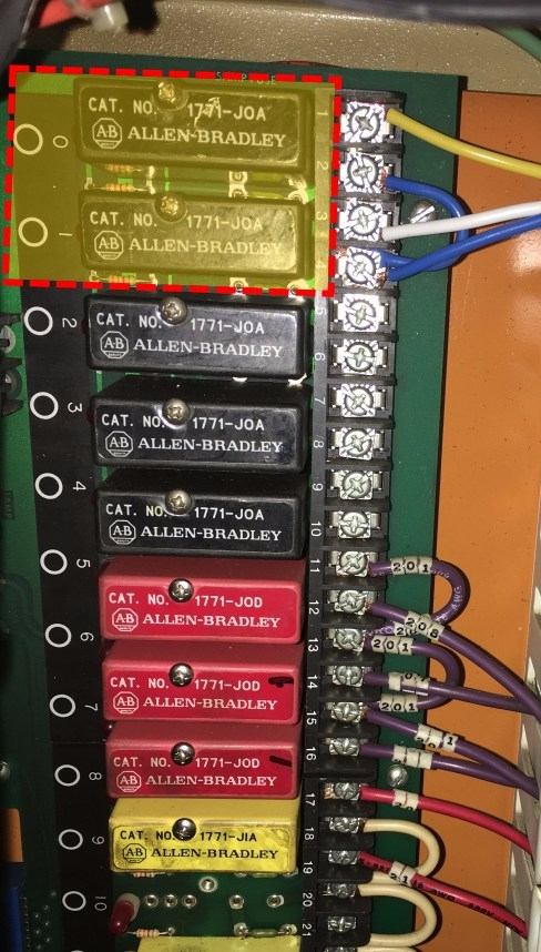 I keep using the slash (output/relay) to indicate that the AB control has digital outputs, and those digital outputs are connected to the relays on an I/O module board. Anyway, I’ve highlighted the two relays being used. The relay identified with a “0” just to the left of it turns the spindle motor on in the one direction. The relay identified with a “1” turns the spindle motor on in the opposite direction. Again, I knew these were the relays to use as they were previously connected to the contactors used to turn on the spindle motor as originally designed. If you notice, the AB control and it’s I/O module board contains a lot of relays that perform other functions. Some of these relays act as inputs to this old mill’s XYZ axis travel limit switches. The picture crops some of these off on the bottom, so there are actually more than shown. I’ve also had to replace a couple of these relays as they can go bad over time – they were old. It wasn’t a big deal really, I found some on eBay reasonably priced.
Okay, finally…here’s some video of the AB control working nicely to control the VFD! If you’re watching the video and wondering what that high pitch whining sound is, it’s not the VFD. It’s one of the servo amplifiers…I don’t like listening to it, but it’s working so I’ll let it be for now.
