With a Variable Frequency Drive (VFD) in hand, as well as some other parts, it was time to start figuring out how to wire things up. To learn more about how I selected the VFD, visit my Discovering the Variable Frequency Drive page.
As built, this old mill’s spindle motor was controlled with contactors. Contactors are basically electronic switches, similar to relays. Contactors and relays are often used to turn on high power circuits with low power control electronics. Specifically for this old mill, it’s Allen Bradley 8400MP control used it’s digital outputs (low power control electronics) to energize some solid state relays wired to contactors to turn the spindle motor on in the forward or reverse direction. The following image is a picture I took of one of the mill’s original power wiring diagrams, and I’ve highlighted areas to help illustrate what I’m talking about. Please note that this old mill’s original power wiring diagrams do not show the digital outputs, or relays previously mentioned. M1F represents the forward spindle motor rotation contactor and M1R represents the reverse contactor. I’m getting ahead of myself, but the Allen Bradley 8400MP digital outputs and relays connected to these contactors turned out to be very useful in working with the VFD, but you’ll have to find the link at the bottom of this page to find out why!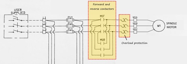
These contactors are no longer needed when using the VFD, as the VFD directly controls the spindle motor’s forward and reverse rotation direction. In fact, the following picture shows all the stuff I removed from this old mill once the VFD was integrated. Well, the prior statement isn’t entirely true on it’s own. If you keep reading this page, you’ll find I replaced many of the fuses in this old mill with breakers – so the picture below shows some of the old din rail mounted fuse blocks too. 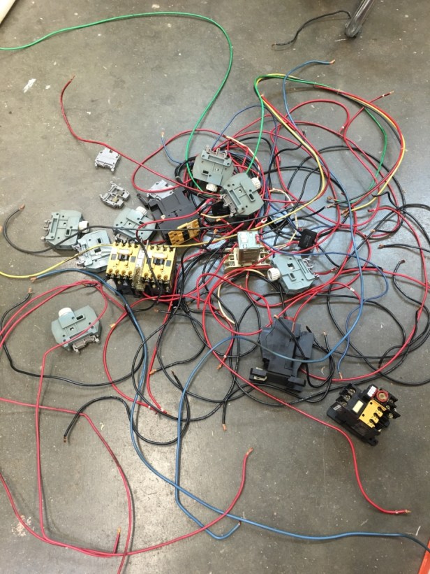 Regardless, all the elements and wiring in the picture above were either associated with controlling the spindle motor or circuit protection (fusing). So how did I know what to remove and what to keep? To be honest it was completely overwhelming to me at first, and I’d be lying if I said I wasn’t afraid of screwing something up. However, I just slowly and carefully worked backwards from the mill’s spindle motor into the mill’s control cabinet. I also knew the spindle motor would be connected directly to the VFD. So it turns out it’s simple. The spindle motor was connected to the contactors previously mentioned, and the contactors were connected to the relays and other things, and those other things were connected to other stuff, and so on – you get the idea here. I also had the mill’s original wiring diagram to look at too, which helped me gain some confidence.
Just so it’s clear, the image below is of the VFD among other power related electrical components mounted in an enclosure. I’ll refer to this as the power enclosure moving forward.
Anyway, the power enclosure is mounted to the side of the mill’s control cabinet as shown (see the big arrow). The cover is removed from the power enclosure, and the VFD is the bright blue box inside of it. The mill came with a power enclosure similar to the one I’ve added, but it was too small to stuff the VFD and other power related items in it. You can’t stuff a 10 lb ham in a 5 lb can ya know!
It might be hard to tell from this picture, but power enters the power enclosure from the bottom via a cord the diameter of a garden hose. The cords leaving the top of the power enclosure provide power to the spindle motor and small spindle cooling fan. Before I move on, it’s not obvious from this picture, but there are also wires passing through a large hole in the side of the power enclosure and into the control cabinet.
So here’s a wiring and equipment diagram showing the new power enclosure I built for the mill. If you’re wondering why I’m going through all this, refer to my How to Power the Beast and Discovering the Variable Frequency Drive pages.  Anyway, the only items I reused from the mill’s original power enclosure are the servo and control transformers. The rest of the items shown in the diagram I purchased new. Starting at the bottom of the inside the enclosure, you can see a distribution block is used to split the incoming power such that it can be routed to the VFD independently of the two transformers. This is absolutely necessary when using a VFD. The VFD can only power the mill’s spindle motor, and absolutely nothing else. A VFD is an electric motor speed/torque controller, not just some sort of power converter. Additionally, I took this opportunity to replace most of the mill’s power related fuses with breakers. Fuses blow (figuratively and literally), and you often never have the size you need when one dies – they ain’t cheap either. The 30A DPST breaker was sized to match the requirements specified in the VFD’s integration manual. At first I didn’t believe a 30A breaker as specified by the VFD manual could possibly be correct. In fact, I called the VFD manufacture curious if it was a typo. Short story, nope, this VFD could draw 30A while starting the 3HP spindle motor. The other two 10A DPST breakers were sized based on the servo and control transformer power ratings. Lastly, I should point out I used dashed lines in the diagram to signify wiring unchanged from the mill’s original power enclosure.
Here’s an actual picture of the power enclosure, I tried to make the diagram above match it within reason. There are some subtle differences, but you get the idea.  I’ll point out here how important grounding is, I used a ground bar (bus bar) to make sure I had a good place to land all the individual ground wires. This method avoids stacking ground wires on top of each other over a ground stud – which I personally dislike. The ground bar is attached directly to the power enclosure mounting plate (metal to metal), and a separate ground wire is purposely connected to the enclosure itself which is good practice and keeps things safe in the case of an accidental short. I’ll admit I was cheap when it came to the enclosure, and purchased one with a lift off cover. If I had to do it over again I probably would have spent a little more money and bought an enclosure with a hinged cover.
Here’s a picture of the power enclosure with the cover installed. As previously mentioned, I went cheap on the enclosure, and purchased one with a lift off cover.  As a result, I ended up going through the effort of putting in a hinged access door directly over the breakers, which is the area I will likely need to get into. Like I said, if I just would have purchased an enclosure with a hinged cover I wouldn’t have gone through this. Just pointing out I ended up spending money and time trying to skimp – something for me to remember and others to think about. Another thing I want to point out, is that I deliberately mounted the VFD to the power enclosure mounting plate on some plastic standoffs.
  This made the VFD protrude through the face of the cover. I just had to cut a hole in the cover that lined up with the VFD, giving me access to it’s controls at all times. Here’s another picture showing the breaker access door open. I also utilized a simple cam latch style lock to keep the door closed. The lock doesn’t require a key to rotate the cam, it has a simple slot on the face you turn with a flat blade screw driver or coin. The breaker access door attaches to the power enclosure cover with a simple piano style hinge. I was just using some stuff I had around the garage, so I’m sure there are some better ways to do all of this.
So you’re probably wondering, cool…but does it work? Heck yeah it works! Click play on the video below showing the spindle motor being controlled by the VFD for the 1st time. Turn your volume up to give you a better idea of the sound and speed of the spindle.
Please note that the time it took for the VFD to ramp the spindle up to full speed is shown at the VFD’s factory setting – which is deliberately setup slow. I’ve since set the ramp-up time to be much faster. The video is a bit long and boring, but if you’re patient you’ll also see me change the spindle motor from rotating in it’s initial direction, to the opposite direction, all just using the VFD controls. I also change the speed of rotation. If you’re wondering what 60 means on the VFD display, it means 60 Hz. 60 Hz is the frequency of the power being sent to the spindle motor, and represents the fastest rotational speed the VFD can drive the spindle motor to – otherwise known as 100%. It’s probably obvious, but anything less than 60 Hz is slower than full speed.
 So what does this mean relative to the spindle motor’s speed? To know for sure you have to look at the identification plate attached to the spindle motor to see an R.P.M value of 1720. By the way, I don’t think there is anything unique about 1720 number of this old mill’s spindle motor, I think it’s pretty typical of 3-phase AC induction motors. When the VFD is at 60 Hz, the spindle motor will be rotating at 1720 Revolutions Per Minute. It’s that simple. For my mill, that doesn’t mean 1720 is the maximum spindle speed, its just the maximum speed of the spindle motor. The spindle itself is coupled to the spindle motor with a mechanical gearbox that allows the spindle to rotate much faster and slower.
OK, so the VFD works, which in my opinion stands as an accomplishment on its own! I certainly could have stopped here and been totally happy with my investment in the VFD. However, being who I am, I wasn’t satisfied yet – I wanted more out of the VFD. I also didn’t like walking away from the mill’s console over to the VFD to start/stop the spindle or change it’s speed. What I did next is what makes the VFD kick the rotary phase converter’s butt – as if it didn’t already. See the Controlling the Variable Frequency Drive page to see how I got this old mill’s Allen Bradley 8400MP control to manage the VFD! You can teach old dogs new tricks.
